ATtiny1614 hello buzzer board
Motivation
For more fun to hello board beyond simple stuff like LED, switch and serial echoing.
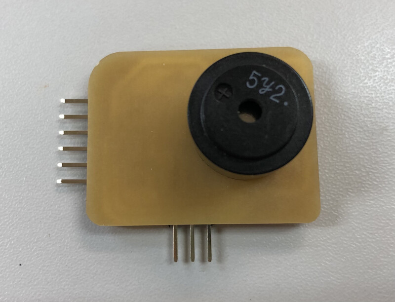
At Fablab kannai inventory, we have electromagnetic buzzer(SDC1614L5-01) and I try to use that to AVR 1 series hello board.
Experiment
Before milling PCB, I checked the behavior of electromagnetic buzzer by ATtiny3216 breakout board and breadboard. This certainly make sounds though tone generation was not stable.
Schematic
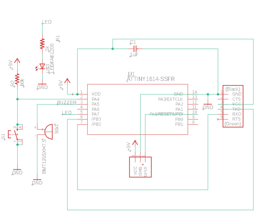
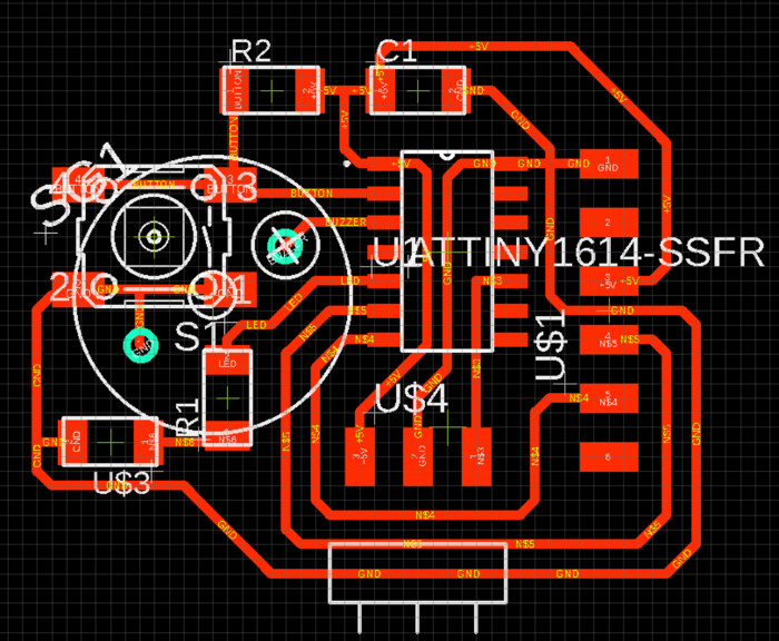
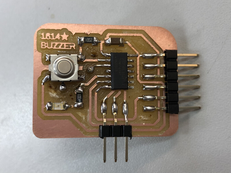
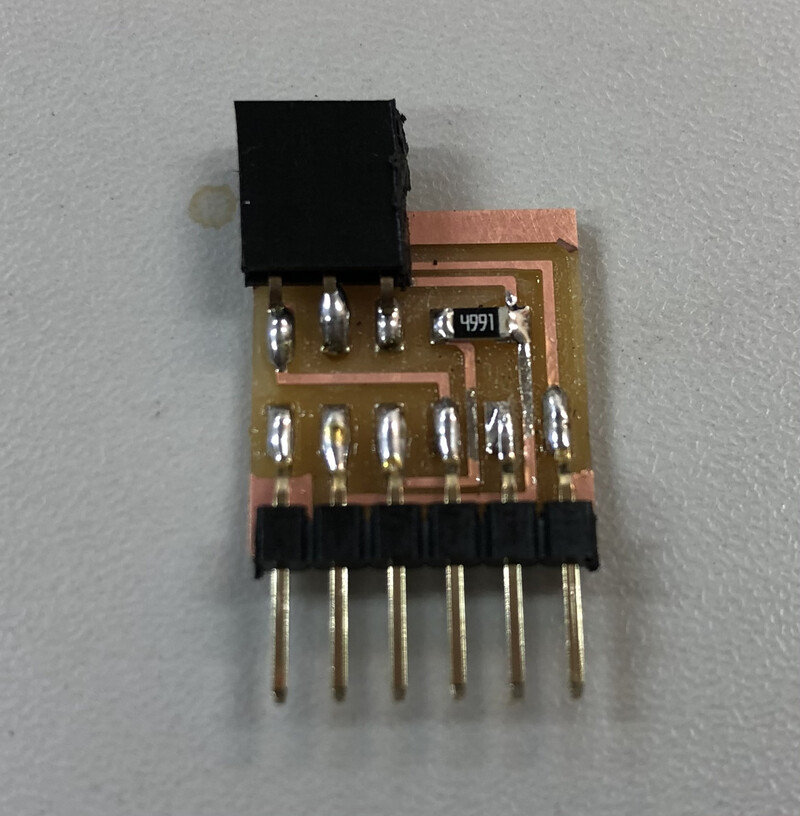
Board
Note
Used different library for buzzer SG1(BMT1205XH7.5) is not the right parts - SDC1614L5-01. For the future electronics design, see TBD section.
Warning
Error of stop mask was raise by DRC. I could not figure out how to solve that and just ignored.
Production on 5 March 2021.
Code
hello.t1614.echo.buzzer.ino pitches.h
1 2 3 4 5 6 7 8 9 10 11 12 13 14 15 16 17 18 19 20 21 22 23 24 25 26 27 28 29 30 31 32 33 34 35 36 37 38 39 40 41 42 43 44 45 46 47 48 49 50 | |
For adding pitches.h file to the code(.ino) on Arduino IDE,
- click triangle under serial monitor mark in Arduino IDE > “New tab”
- Input the name - “pitches.h”
- At “pithces.h” tab, paste the code of pitches.h
Ref. Play a Melody using the tone() function
Write program
Used pyupdi. We may upload program directly from Arduino IDE. See TBD(#tbd).
Setup Arduino IDE board manager and build path for build .hex files
After configuring Arduino IDE, click “check” button on Arduino code editor. Then you can see .hex file at your build path on your machine.
Setup pyupdi
On your terminal (Mac terminal, Windows gitbash or powershell), make python virtual environment and activate that. Python virtual environment helps to solve library dependencies and path for commandline.
1 2 3 4 5 6 7 8 9 10 11 | |
Run pyupdi
If you are not on python virtual environment,
1 2 3 4 | |
Connecting UPDI interface to target board from programmer board (over FTDI), write .hex file via pyupdi.
1 2 | |
If puypdi works, terminal output shows like:
1 2 | |
BoM
| Part | Value | Device | Package | Description | BUILT_BY | MEMO |
|---|---|---|---|---|---|---|
| C1 | 1uF | CAP_UNPOLARIZEDFAB | C1206FAB | |||
| R1 | 1k | R1206FAB | R1206FAB | Resistor (US Symbol) | ||
| R2 | 10k | R1206FAB | R1206FAB | Resistor (US Symbol) | ||
| S1 | SW_SWITCH_TACTILE_6MM6MM_SWITCH | 6MM_SWITCH | OMRON SWITCH | |||
| SG1 | SDC1614L5-01 | SDC1614L5-01 | SDC1614L5-01 | MAGNETIC TRANSDUCER | BMT1205XH7.5 on above board image is “BMT1205XH7.5”. See TBD(#tbd) | |
| U$1 | CONN_06_FTDI-SMD-HEADER | CONN_06_FTDI-SMD-HEADER | 1X06SMD | |||
| U$3 | LEDFAB1206 | LEDFAB1206 | LED1206FAB | LED | ||
| U$4 | UPDI_3POS_SMD_SHAPE | UPDI_3POS_SMD_SHAPE | 1X03SMD | |||
| U1 | ATTINY-SSFR | ATTINY1614-SSFR | SOIC14_SL | EMA_Molly | Copyright (C) 2018 Accelerated Designs. All rights reserved |
TBD
- To change size of buzzer foot print : Actual footprint width between two leges for buzzer(SDC1614L5-01) is 5.7mm than EAGLE library parts that I used above(7.2mm). We should shorten the width between the holes for buzzer foot.
- Tamiya-san made EAGLE lbr file for SDC1614L5-01(5 March 2021)
- To use 6 pin angle header with support part on EAGLE board : (EAGLE lbr file for SDC1614L5-01 that Tamiya-san made would help to check size of board outline.
- To solve “Error of stop mask by DRC” : Maybe the problem of selected library? When I used (ATtiny1614.lbr)[http://academany.fabcloud.io/fabacademy/2021/labs/kannai/site/instruction/tips/eagle_lib/ATtiny1614.lbr], I did not see that error.
- To use internal pullup on ATtiny1614 for switch : ATtiny1614 has internal pullup and we may use that instead of adding pullup resister.
- To upload program directly from ArduinoIDE : On 5 March 2021 local session at Fablab Kannai, we could not uplaod using megaTinyCore Board Manager(ver2.2.5 or later) and could write program by pyupdi.
Files
Eagle
Source files
Reference
- Electronics design, Fab Academy 2021 locall session at Kannai
- SpenceKonde/megaTinyCore
- ブザーの基本 - テクノロジー、トーン、駆動回路
- EAGLE community - error of stop mask
- Play a Melody using the tone() function