Bubble Machine Prototype
What’s this?
This is prototype’s prototype of “Bubble machine(仮)”, Fab Acadmey 2021 machine building project at Fablab Kannai, for experimenting minimal electronics and software implementation.
Materials
- v0.1~
- Arduino Uno Rev3 (Compatible)
- Stepper motor - KH42KM2-802 (日本電産サーボ 2相ステッピングモータ)
- Unipolar (can be used as bipolar)
- Step angle: 1.8 (=200 steps/rev.)
- Shaft diameter: 5mm
- Voltage 12V, Current 0.4A, Winding resistance 30Ω
- Holding torque: 3.2 kgf·cm
- datasheet p5-6
- Motor Driver - HiLetgo RepCap A4988
- AC Aapter(12V)
- Adaptor conversion plug (5.5mm x 2.1mm DC 12V)
- Servo Motor ー Micro Servo SG90
- Operating voltage 3.3V-6V
- Stall torque: 1.8 kgf·cm
- datasheet
- X-axis rail frame (from FabAcademy 2020 - Slide Guitar Machine)
- Breadboard
- Jumper cables
- v0.2~
- Tactile switch(12mm) - TVGP01-G73BB
- LED x 2 (red, clear-red)
- 220Ω resister x 2
- v0.4~
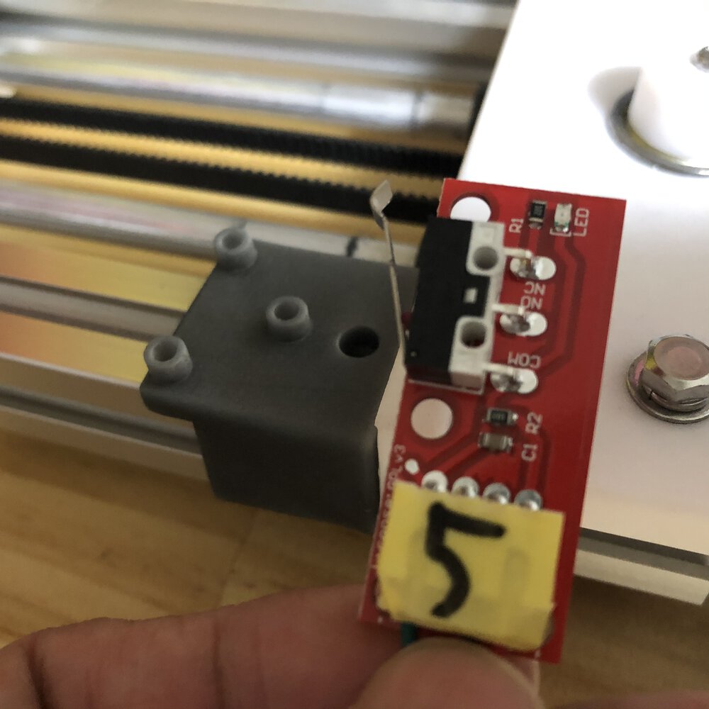
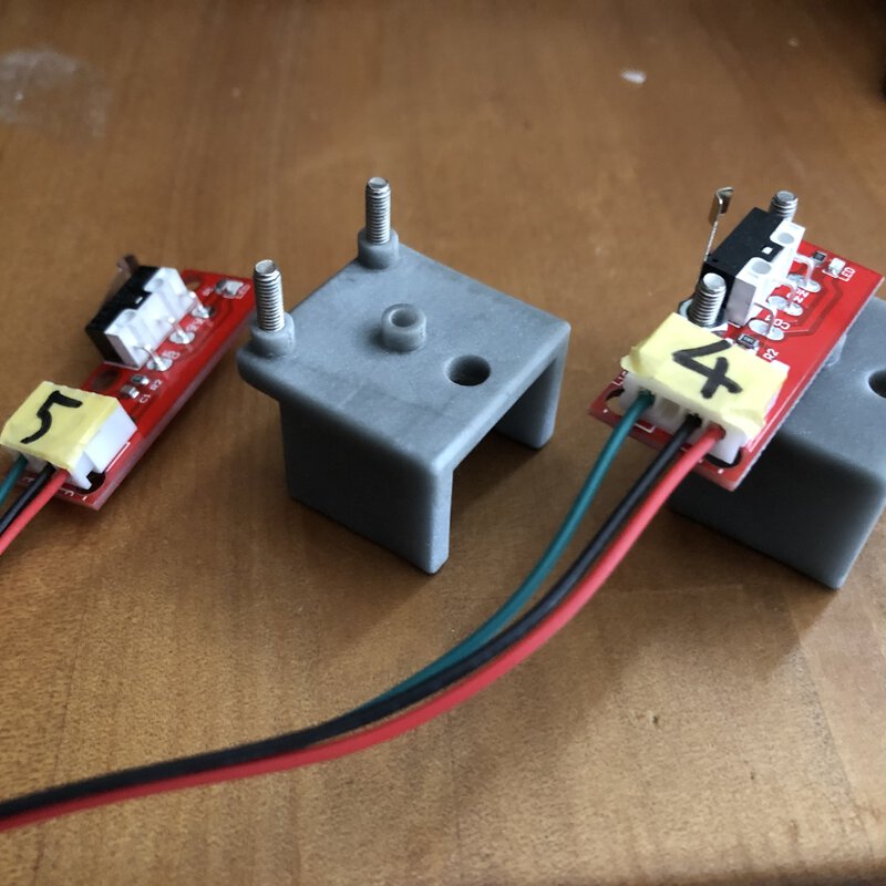
- Limit switch - TOOHUI - T241
- Wire Type: 22AWG
- Working voltage: 300 V, Working current: 2A
- Temperature resistance: 80 degrees Celsius
- Red line connects to VCC (Ramp +)
- Black line connects to GND (Ramp - )
- Green line connects to signal (lamps)
- Cable Length: about 70cm/27.56”
- Supports use of RAMPS 1.4 plates.
- Limit switch - TOOHUI - T241
- v0.6~
- Attachment for Limit switches
v0.1 - Stepper & servo motors
Composition and behavior
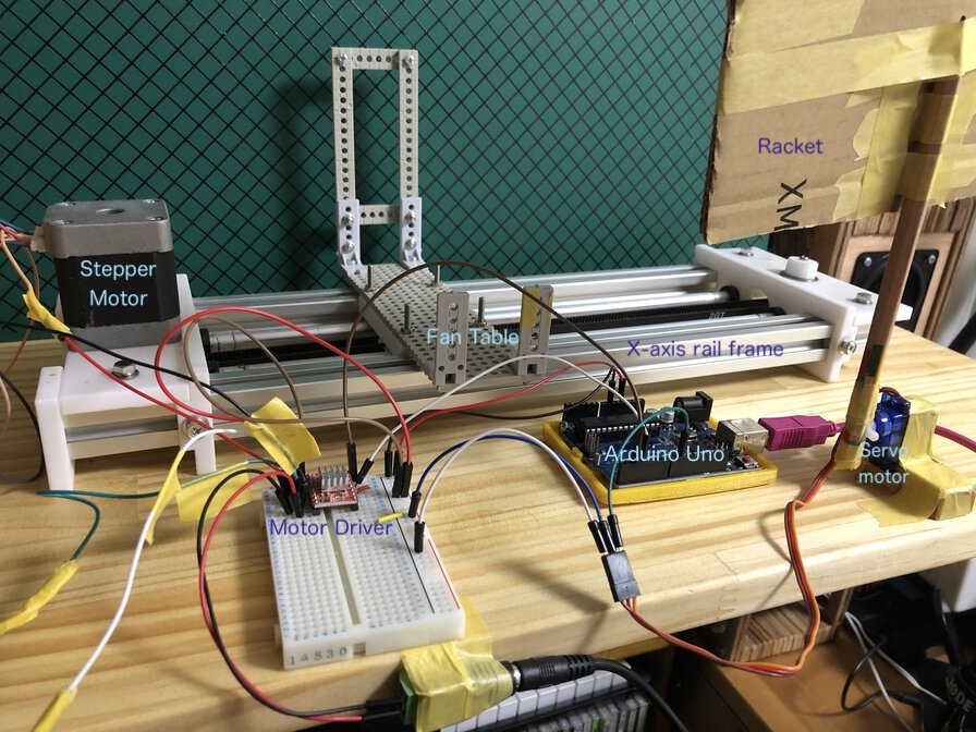
- Motor Driver and Stepper motor operate fan table on X-axis rail frame
- When a rotary fan table comes to the racket position, racket is tilted up to 90 degree
- (Rotary fan is running continuously and when racket with soap faces toward the front, soap bubble is blew production only)
- Application program is embedded in Arduino Uno
Electronics
Power supply
- 12V-1.0A AC Adapter for powering stepper motor
-
5V (from Arduino Uno, up to 200mA) for servo motor
-
There are no information about current in datasheet, some website tells about current for SG90: Ref.Proto Supplies
SG90 Measure value Voltage 4.8-6VDC (5V Typical) Current (idle) 10mA (typical) Current (typical during movement) 100-250mA Current (stall) 360mA (measured) Stall Torque 1.7 kg-cm (measured) Speed 0.12s / 60 degree (varies with VDC)
-
-
5V(from ARduino Uno) for data control circuit
Pin map v0.2
| Arduino | A4988 | Stepper motor | Servo motor |
|---|---|---|---|
| 2 | 7)STEP | ||
| 3 | 8)DIR | ||
| 9 | PWM | ||
| 5V | 10)VDD | VCC | |
| GND | 9)GND | Ground | |
| 16)VMOT - to 12V AC Adapter | |||
| 15)GND - to 12V AC adapter ground | |||
| 14)2B | black | ||
| 13)2A | brown | ||
| 12)1A | yellow | ||
| 11)1B | orange |
Ref.
- lastminuteengineers.com - Control Stepper Motor with A4988 Driver Module & Arduino
- Originalmind.co.jp - Arduinoでメカトロニクス製品を動かそう
- Tatsuro Homma FA2020 machine building page
Motor Driver (A4988) setup
- Put heat sink
- Current limiting
- Ref.
- FA2020 - Stepper Motor
- “Current Limiting section in “Tutorial in lastminuteengineers.com
- Ref.
Source Code v0.1
1 2 3 4 5 6 7 8 9 10 11 12 13 14 15 16 17 18 19 20 21 22 23 24 25 26 27 28 29 30 31 32 33 34 35 36 37 38 39 40 41 42 43 44 45 46 47 48 49 50 51 52 53 54 55 56 57 58 | |
Outcome - as of 2021.03.27
v0.2 - Add switch
Composition and behavior
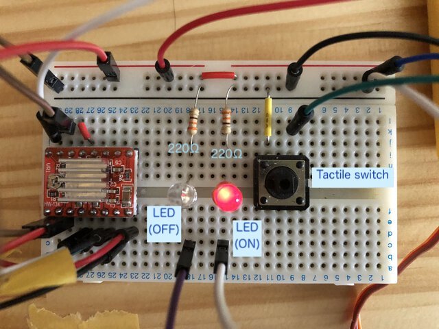
Added minimal function to start / stop stepper and servo motors by minimal materials (tactile switch and LEDs).
- Why?
- To control the position of fan table and angle of racket whenever start/stop machine, ideally. Without start / stop function, I need to calibrate the position of that moving parts by hand every time.
Electronics
Power supply
- Used internal pullup of Arduino digital pin.
- LED power is from Arduino data control pin.
Pin map v0.2
| Arduino | A4988 | Stepper motor | Servo motor | Others | Memo |
|---|---|---|---|---|---|
| 2 | 7)STEP | ||||
| 3 | 8)DIR | ||||
| 9 | PWM | ||||
| 5V | 10)VDD | VCC | |||
| GND | 9)GND | Ground | |||
| 16)VMOT - to 12V AC Adapter | |||||
| 15)GND - to 12V AC adapter ground | |||||
| 14)2B | black | ||||
| 13)2A | brown | ||||
| 12)1A | yellow | ||||
| 11)1B | orange | ||||
| 7(INPUT_PULLUP) | Tactile switch | New! | |||
| 12 | LED(red) - on | New! | |||
| 13 | LED(clear-red) - off | New! |
Source Code v0.2
1 2 3 4 5 6 7 8 9 10 11 12 13 14 15 16 17 18 19 20 21 22 23 24 25 26 27 28 29 30 31 32 33 34 35 36 37 38 39 40 41 42 43 44 45 46 47 48 49 50 51 52 53 54 55 56 57 58 59 60 61 62 63 64 65 66 67 68 69 70 71 72 73 74 75 76 77 78 79 80 81 82 83 84 85 86 87 88 89 90 91 92 | |
Outcome - as of 2021.03.29
v0.3 - Use Stepper library and implement “homing” logic
For coding easily, it looks good to use Stepper library in Arduino standard library.
It’s important to homing (return to initial position when switch off) for calibrating machine smoothly.
Homing (return to initial Position)
As per Arduino forum - Stepper Motor Basics,
Position Feedback
Stepper motors do not have the ability to tell the Arduino what position they are at, nor do they have the ability (like a servo) to go to a particular position. All they can do is move N steps from where they are now.
If it is essential to have position feedback a rotary encoder can be attached to the motor shaft - but that is beyond the scope of this essay.
Initial Position
When it starts up the Arduino has no means of knowing where the stepper motor is positioned - for example somebody might have moved it manually when the power was off.
The usual way to establish a datum for counting steps is with a limit switch. At startup the Arduino will move the motor until it triggers the switch. The Arduino will then regard that step position as step zero for the purpose of future position keeping.
Note
It’s necessary to keep how many steps forward it has taken. When “stop” switch is toggled, reverse the count and motor comes to zero position.
RPM
RPM (Round per minute) is calculated by:
60 x (steps per second / steps per revolution)
Ref. Sciencing - Calcuating RPMs for Stepper Motors
In case of KH42KM2-802 on prototype machine,
- steps per second : measured at v0.2 example as
800 steps/1.75 seconds ≒ 457 - steps per revolution :
200
60 x (457 / 200) ≒ 137
Warning
This value totally is not right. Actual source code works by smoothly 500 RPM It may be because v0.2 works by 1 millisecond delay for each digitalWrite() and need to add the other overhead.
Source code v0.3
1 2 3 4 5 6 7 8 9 10 11 12 13 14 15 16 17 18 19 20 21 22 23 24 25 26 27 28 29 30 31 32 33 34 35 36 37 38 39 40 41 42 43 44 45 46 47 48 49 50 51 52 53 54 55 56 57 58 59 60 61 62 63 64 65 66 67 68 69 70 71 72 73 74 75 76 77 78 79 80 81 82 83 84 85 86 87 88 89 90 91 92 93 94 95 96 97 98 99 100 101 102 103 104 105 106 107 108 109 110 111 112 113 114 115 116 117 118 119 120 121 122 123 124 125 126 127 128 129 130 131 132 133 134 135 136 137 138 139 140 141 142 | |
Outcome as of 2021.03.30
v0.4 Experiment limit switch (hit back motor direction)
Composition and behavior
For edge detection by limit switch, I experimented one limit switch to control stepper motor.
Pin map v0.4
| Arduino | A4988 | Stepper motor | Servo motor | Others | Memo |
|---|---|---|---|---|---|
| 2 | 7)STEP | ||||
| 3 | 8)DIR | ||||
| 4 | Limit Switch | v0.4 | |||
| 9 | PWM | ||||
| 5V | 10)VDD | VCC | VCC for LED,Tact switch,Limit switch | ||
| GND | 9)GND | Ground | GND for LED,Tact switch,Limit switch | ||
| 16)VMOT - to 12V AC Adapter | |||||
| 15)GND - to 12V AC adapter ground | |||||
| 14)2B | black | ||||
| 13)2A | brown | ||||
| 12)1A | yellow | ||||
| 11)1B | orange | ||||
| 7(INPUT_PULLUP) | Tactile switch | v0;2 | |||
| 12 | LED(red) - on | v0.2 | |||
| 13 | LED(clear-red) - off | v0.2 |
Source code v0.4
1 2 3 4 5 6 7 8 9 10 11 12 13 14 15 16 17 18 19 20 21 22 23 24 25 26 27 28 29 30 31 32 33 34 35 36 37 38 39 40 41 42 43 44 45 46 47 48 49 50 51 52 53 54 55 56 57 58 59 60 61 62 63 64 65 66 67 68 69 70 71 72 73 74 75 76 77 78 79 80 81 82 83 84 85 86 87 88 89 90 91 92 93 94 95 96 97 98 99 100 101 102 103 104 105 106 107 108 109 110 111 112 113 114 115 116 117 118 119 120 121 122 123 124 125 126 127 128 129 130 131 132 133 134 135 136 137 138 139 140 141 142 143 144 145 146 147 148 149 150 151 152 153 154 155 156 157 158 159 160 161 162 | |
Outcome as of 2021.03.31
v0.5 Toggle motor direction by two limit switches
Composition and behavior
- On startup, to move the motor until it triggers the switch. The Arduino will then regard that step position as step zero for the purpose of future position keeping.
- Two limit switches toggle the direction to move stepper motor
Pin map v0.5
| Arduino | A4988 | Stepper motor | Servo motor | Others | Memo |
|---|---|---|---|---|---|
| 2 | 7)STEP | ||||
| 3 | 8)DIR | ||||
| 4 | Limit Switch | v0.4 | |||
| 5 | Limit Switch | v0.5 | |||
| 9 | PWM | ||||
| 5V | 10)VDD | VCC | VCC for LED,Tact switch,Limit switch | ||
| GND | 9)GND | Ground | GND for LED,Tact switch,Limit switch | ||
| 16)VMOT - to 12V AC Adapter | |||||
| 15)GND - to 12V AC adapter ground | |||||
| 14)2B | black | ||||
| 13)2A | brown | ||||
| 12)1A | yellow | ||||
| 11)1B | orange | ||||
| 7(INPUT_PULLUP) | Tactile switch | v0;2 | |||
| 12 | LED(red) - on | v0.2 | |||
| 13 | LED(clear-red) - off | v0.2 |
Source code v0.5
Outcome as of 2021.04.01
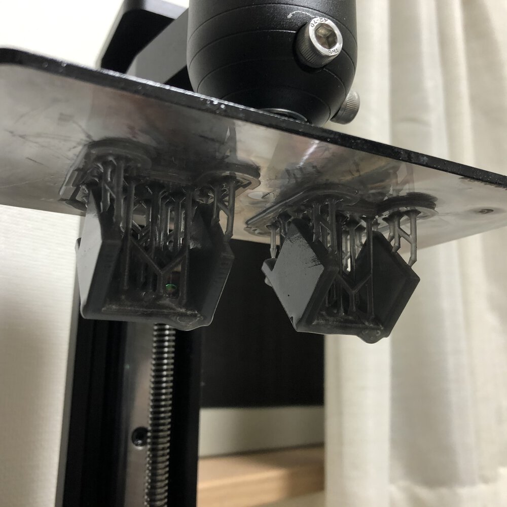
v0.6 Use limit switches for edge collision detection
3D printed attachment for limit switch
For attaching limit switches to rail frame, made an attachment that fits with 20x20 aluminum frame.
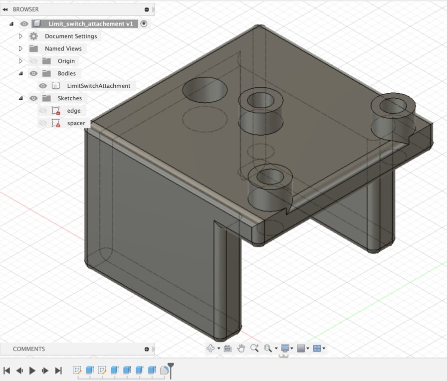

3D model on Autodesk A360
Composition and behavior

- On power on, stepper automatically goes to edge “UP”, turns to edge “Down”, then go to home position. Software checks how many steps it takes from “UP” to “Down”, then sets positions(absolute step numbers). Below is from log message in Serial monitor output:
 1
 2
 3
 4
 5
 6
 7
 8
 9
10
23:53:40.346 -> edgeUp collision detected 23:53:40.346 -> Detected step_end position (edgeUp) is: 1186 23:53:42.796 -> edgeUp collision detected 23:53:42.796 -> Detected steps_begin positon (edgeDown) is: -2876 23:53:42.796 -> ---Adjusted steps positions--- 23:53:42.796 -> steps_begin: 0 // edge "Down" position 23:53:42.796 -> steps_home: 200 // home position 23:53:42.796 -> steps_turn: 3862 // the place where servo rotates and table head turns 23:53:42.796 -> steps_end: 4062 // edge "Up" position 23:53:42.796 -> ------------------------------ - If anything wrong and table head touch with limit switches, table head automatically goes to home position and stop stepping motor.
Source code v0.6
Outcome as of 2021.04.02
Files
Reference
- Fablab Kannai Fab Academy 2021 - Instruction/week09 Mecanical design & Machine design
- Tatsuro Homma FA2020 machine building page
- lastminuteengineers.com - Control Stepper Motor with A4988 Driver Module & Arduino
- Originalmind.co.jp - Arduinoでメカトロニクス製品を動かそう
- TechWeb motor 基礎知識 ステッピングモーター
- Instructable circuits - Arduino Powered Three Arm Bubble Machine
- Arduino forum - Stepper Motor Basics
- Calcurating RPM stepper motor
- SMART DIYs - Arduiono Uno + A4988でステッピングモーター制御