OLED example
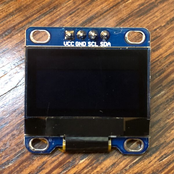
Device

Specification
- Size: 0.96 inch
- Resolution: 128 x 64
- Color: Blue & Yellow
- Visible angle: 160 degrees or more
- Support platforms: arduino 51 series, MSP430 series, STM32/2, CSR chip, etc.
- Ultra low efficiency consumption: normal 0.04 W.
- Wide voltage support: DC 3.3V-5V
- Drive Chip: SSD1306
- Communication Method: IIC, I/O ports only 2
- No font: take software word
Pins
- VCC: 3.3V-5V
- GND: Power Ground
- SCL: CLK Serial
- SDA: Serial Data
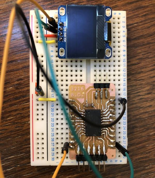
Circuit
- adafruit_products_0-96in_OLED_sch.png
- 10kΩ pull-up resisters for SCL and SDA are assembled on the board
Client environment
- IDE: Arduino IDE 1.8.10 (on MacOS Catalina 10.15.7)
- Board: ATtiny3216 breakout board
- Libraries:
- Adafruit SSD1306 ver. 2.4.4
- Adafruit GFX-Library ver. 1.10.7
Networking
I2C address
Check I2C address by the position of 0Ω resister in “Address Select” area at OLED.
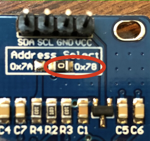
| position | I2C address | memo |
|---|---|---|
| 0x78 | 0x3C | <– |
| 0x7A | 0x3A |
Pin map
| PORT PIN | ATtiny3216 | OLED | Memo |
|---|---|---|---|
| VCC | VIN(+5V) | +5V: 6-pin FTDI-Serial, 3pin UPDI programmer | |
| GND | GND | GND | Ground: 6-pin FTDI-Serial, 3pin UPDI programmer |
| PB0 | SCL | SCL | |
| PB1 | SDA | SDA | |
| PB2 | (7, TXD) | 6-pin FTDI-Serial | |
| PB3 | (6, RXD) | 6-pin FTDI-Serial | |
| PA0 | (17, UPDI) | 3pin UPDI programmer |
Program
Install libraries
Arduino IDE > Tool > Manage Libraries…
- Adafruit SSD1306 ver. 2.4.4
- Adafruit GFX-Library ver. 1.10.7
(Optional) Check library source code
Note
Some old sample requires to change the definition of I2C address in Adafruit_SSD_1306.h. However, it seems current library does not require that (there are no field to define I2C address at the header file. )
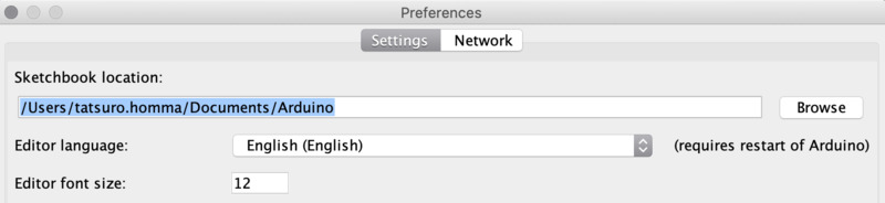
Library file is located at the place like <the sketch location path>/libraries/Adafruit_SSD1306
Sketch location is at Arduino IDE > preferences > sketchbook location
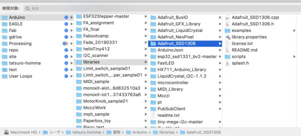
Program (edit example)
Arduino IDE > File > Examples > Adafruit SSD 1306 > ssd1306_128x64_i2c
Change the line arround line no:35
-
Before
1#define SCREEN_ADDRESS 0x3D -
After
1#define SCREEN_ADDRESS 0x3C
I2C address conversion
“0x78” address on OLED board is 7bit mode + 1 bit R/W#bit at the end.
- 0x78 = 0b01111000 <- the last bit(0111100”0”) is “R/W#bit”.
Wire.beginTransmission(address)in Arduino Wire library (used inAdafruit_SSD1306 display()) requires address parameter in 7 bit.- For doing this, dropping the last bit (meaning shift the value one bit to the right)
- 0b01111000
- 0b0111100 = 0x3C, dropped the last bit
Ref. Wire library
There are both 7- and 8-bit versions of I2C addresses. 7 bits identify the device, and the eighth bit determines if it’s being written to or read from. The Wire library uses 7 bit addresses throughout. If you have a datasheet or sample code that uses 8 bit address, you’ll want to drop the low bit (i.e. shift the value one bit to the right), yielding an address between 0 and 127. However the addresses from 0 to 7 are not used because are reserved so the first address that can be used is 8.
Write program by UPDI
- Arduino IDE > Tool
- Board: ATtiny3216
- Port: /dev/cu.usbserial-D307RG9Y
- Programmer: “Serial Port and 4.7k(pyupdi style)”
Then write program by “Upload” function
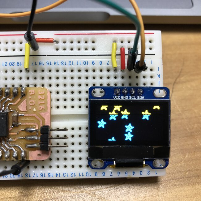
Outcomes
ssd1306_128x64_i2c
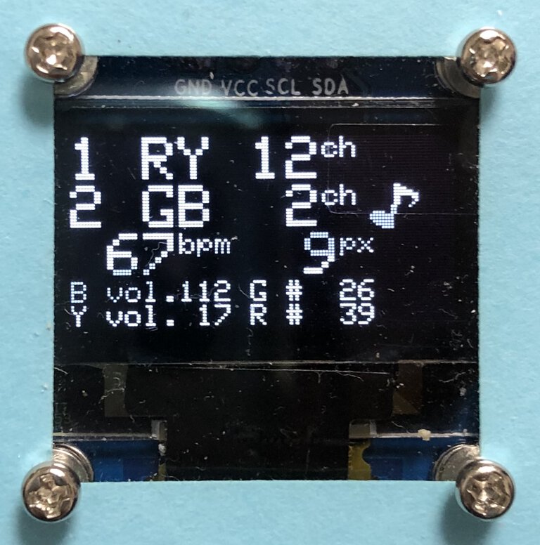
PoTone display, FA2020 :)
The other tips
- Pullup resister for I2C
You must be sure to use external pullup resistors on the SDA and SCL lines if the devices you are connecting do not have those on board (many Arduino/hobby targeted breakout boards do - typically 10k - though these may need to be enabled with a solder-bridge or jumper). The 30k-50k internal pullup resistors are not suitable for I2C pullup resistors; while they were enabled by megaTinyCore prior to version 2.1.0, this was the worst of both worlds: they often did work with the simple test case, leading the developer on their merry way thinking they were all set, only to discover that when they added another I2C device or two, or moved the device to the end of a longer cable, I2C suddenly no longer worked - it’s probably better for it to fail immediately, prompting investigation and subsequent addition of appropriate pullup resistors.
- SpenceKonde/megaTinyCore#i2c-twi-support - TWI Pins: Switch SCL/SDA pins to the other set by
Wire.swap(1) or Wire.swap(0). It looks default(0) means PB0: SCL, PB1: SDA on Attiny3216
References
- learn.adafruit.com - Arduino Library & Examples
- adafruit_products_0-96in_OLED_sch.png
- adafruit OLED breakout - download
- Wire library
- Adafruit_SSD1306 Class reference
- Qiita - ArduinoでOLEDディスプレイを試す
- mgo-tec電子工作 - 有機EL ( OLED ) SSD1306 を再検証してみました ( I2C 通信用 )
- http://www.picfun.com - I2C通信の使い方