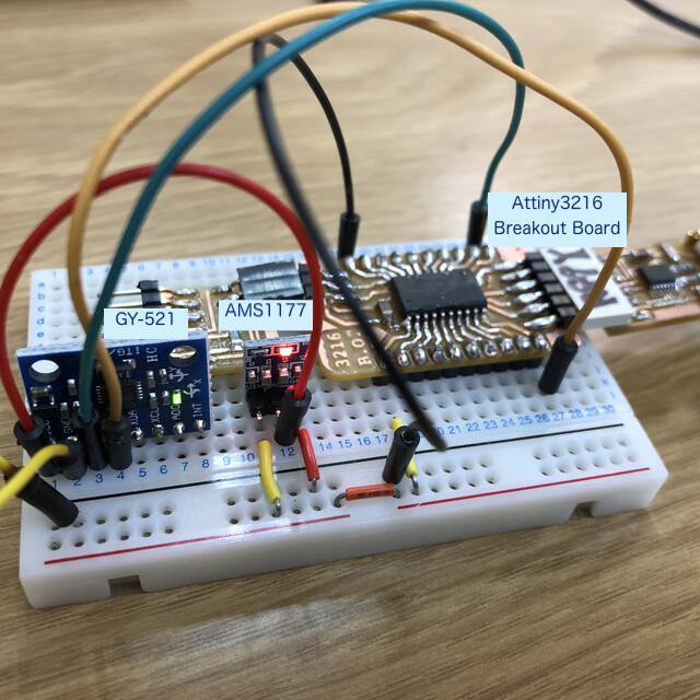
Attiny3216 6-axis accelerometer+gyroscope
Materials
Component
Pin map
| PORT PIN |
Arduino |
AMS1177(5>3.3 Step down) |
GY521 |
Memo |
| VCC |
|
VIN(+5V) |
|
+5V: 6-pin FTDI-Serial, 3pin UPDI programmer |
| GND |
|
GND |
GND |
Ground: 6-pin FTDI-Serial, 3pin UPDI programmer |
|
|
VOUT(3.3V) |
VCC(3.3V) |
|
| PB0 |
SCL |
|
SCL |
|
| PB1 |
SDA |
|
SDA |
|
| PB2 |
(7, TXD) |
|
|
6-pin FTDI-Serial |
| PB3 |
(6, RXD) |
|
|
6-pin FTDI-Serial |
| PA0 |
(17, UPDI) |
|
|
3pin UPDI programmer |
Source code
 1
 2
 3
 4
 5
 6
 7
 8
 9
10
11
12
13
14
15
16
17
18
19
20
21
22
23
24
25
26
27
28
29
30
31
32
33
34
35
36
37
38
39
40
41
42
43
44
45
46
47
48
49
50
51
52
53
54
55
56
57
58
59
60 | #include <Wire.h>
// MPU-6050 Address, register
#define MPU6050_WHO_AM_I 0x75 // Read Only
#define MPU6050_PWR_MGMT_1 0x6B // Read and Write
#define MPU_ADDRESS 0x68
// I2C Initialization
void setup() {
Wire.begin();
Serial.begin(115200);
// Read at the first time
Wire.beginTransmission(MPU_ADDRESS);
Wire.write(MPU6050_WHO_AM_I); //MPU6050_PWR_MGMT_1
Wire.write(0x00);
Wire.endTransmission();
Wire.beginTransmission(MPU_ADDRESS);
Wire.write(MPU6050_PWR_MGMT_1); //MPU6050_PWR_MGMT_1 register
Wire.write(0x00);
Wire.endTransmission();
}
void loop() {
Wire.beginTransmission(0x68);
Wire.write(0x3B);
Wire.endTransmission(false);
Wire.requestFrom(0x68, 14, true);
while (Wire.available() < 14);
int16_t axRaw, ayRaw, azRaw, gxRaw, gyRaw, gzRaw, Temperature;
axRaw = Wire.read() << 8 | Wire.read();
ayRaw = Wire.read() << 8 | Wire.read();
azRaw = Wire.read() << 8 | Wire.read();
Temperature = Wire.read() << 8 | Wire.read();
gxRaw = Wire.read() << 8 | Wire.read();
gyRaw = Wire.read() << 8 | Wire.read();
gzRaw = Wire.read() << 8 | Wire.read();
// Convert the acceleration value to acceleration (G) by dividing it by the resolution
float acc_x = axRaw / 16384.0; //FS_SEL_0 16,384 LSB / g
float acc_y = ayRaw / 16384.0;
float acc_z = azRaw / 16384.0;
// Convert angular velocity value to angular rate (degrees per sec) by dividing it by resolution.
float gyro_x = gxRaw / 131.0;//FS_SEL_0 131 LSB / (°/s)
float gyro_y = gyRaw / 131.0;
float gyro_z = gzRaw / 131.0;
Serial.print("a_X: "); Serial.print(acc_x);
Serial.print("| a_Y: "); Serial.print(acc_y);
Serial.print("| a_Z: "); Serial.print(acc_z);
Serial.print("| g_X: "); Serial.print(gyro_x);
Serial.print("| g_Y: "); Serial.print(gyro_y);
Serial.print("| g_Z: "); Serial.print(gyro_z); Serial.println("");
delay(250);
}
|
Serial monitor result - tilt x axis:
| a_X: -0.07| a_Y: 0.21| a_Z: 1.06| g_X: 10.83| g_Y: 40.21| g_Z: 42.64
a_X: 0.23| a_Y: 0.06| a_Z: 1.03| g_X: -5.82| g_Y: -202.69| g_Z: -22.91
a_X: 1.42| a_Y: 0.24| a_Z: 0.00| g_X: 16.92| g_Y: -91.81| g_Z: 75.99
a_X: 0.65| a_Y: 0.04| a_Z: -0.40| g_X: 16.58| g_Y: -250.14| g_Z: 91.08
a_X: 0.81| a_Y: 0.05| a_Z: -0.76| g_X: -39.05| g_Y: 250.13| g_Z: -114.60
a_X: 0.44| a_Y: 0.09| a_Z: 0.49| g_X: 6.44| g_Y: 9.58| g_Z: 37.79
a_X: 0.69| a_Y: -0.53| a_Z: 0.28| g_X: -114.76| g_Y: -21.26| g_Z: 227.22
a_X: 0.49| a_Y: -0.98| a_Z: 0.20| g_X: -109.78| g_Y: 7.98| g_Z: 100.63
a_X: 0.54| a_Y: -1.21| a_Z: -0.14| g_X: -22.50| g_Y: 10.28| g_Z: -250.14
a_X: 1.31| a_Y: 0.24| a_Z: 0.28| g_X: 81.44| g_Y: 14.50| g_Z: -250.14
...
|
Consideration
Warning
- GY521 might work by +5V VCC by some instruction.
- GY521 module for this experiment is not stable. When power plug-in Attiny3216 breakout board, Serial value shows zero. After Plug-off and plug-in FTDI cable several times, Serial monitor shows the sensor value.
Outcome as of 2021.04.15
Reference
Last update: April 15, 2021